

Understanding Your Vehicle: A Complete Car Exhaust System Diagram Explained. Navigating the inner workings of your vehicle can feel like exploring a complex maze of metal and mechanics. One of the most vital systems that often remains behind the scenes is the exhaust system. This article breaks down the intricacies of your car’s exhaust system using a comprehensive Exhaust System Diagram, simplifying the technical details into friendly, easy-to-understand language.
Exhaust System Diagram – The Basics Revealed
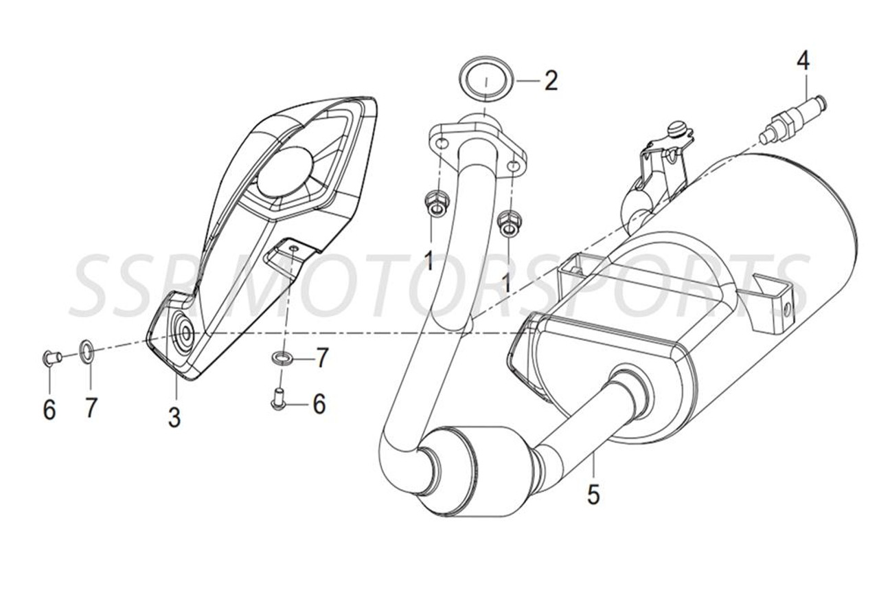
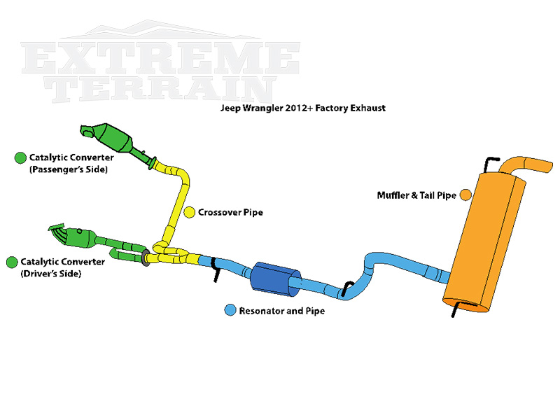
The first step in understanding your vehicle’s exhaust system is to break down what each component does. The Exhaust System Diagram illustrates the journey of exhaust gases starting from the engine, through various components, and finally out of the tailpipe. The diagram typically includes the exhaust manifold, catalytic converter, muffler, and tailpipe. Each section plays a critical role in ensuring efficient engine performance, reducing harmful emissions, and minimizing engine noise.
At its core, the exhaust system collects waste gases produced during combustion and channels them away from the engine. The diagram helps visualize how these components work together. For instance, the exhaust manifold collects gases from each cylinder and directs them into a single pipe. Understanding this flow can help you diagnose potential issues such as backpressure, leaks, or blockages, which might affect your vehicle’s performance.
Exhaust System Diagram – The Role of the Exhaust Manifold
In any Exhaust System Diagram, the exhaust manifold is depicted as the starting point of the system. This component is attached directly to the engine’s cylinder head and collects exhaust from multiple cylinders. Its design and material matter because it needs to withstand high temperatures and repeated thermal expansion and contraction.
A well-designed exhaust manifold optimizes the flow of gases out of the engine, reducing engine backpressure. With less backpressure, the engine can operate more efficiently, improving fuel economy and power output. Sometimes, enthusiasts look at upgraded headers—essentially high-performance versions of the exhaust manifold—to boost performance. In the context of our Exhaust System Diagram, this crucial component is the foundation upon which the rest of the system is built. (Read More: Car Exhaust Leak Repair: Symptoms and How To Fix It).
Exhaust System Diagram – Catalytic Converter’s Function
Moving further along in the Exhaust System Diagram, the catalytic converter is a star player in reducing pollution. Positioned downstream from the exhaust manifold, it transforms harmful pollutants into less toxic emissions before they exit your vehicle. (Read More: Car Brand Logos Horse: A Mark of Strength and Luxury).
Inside the catalytic converter, a series of chemical reactions occurs. The converter contains precious metals like platinum, palladium, and rhodium that serve as catalysts. These materials encourage reactions that convert carbon monoxide, unburned hydrocarbons, and nitrogen oxides into carbon dioxide, water vapor, and nitrogen. This process is essential not only for environmental reasons but also to ensure your vehicle meets regulatory standards for emissions.
Exhaust System Diagram – Muffler Magic
A common point of interest in many Exhaust System Diagrams is the muffler. This component is often associated with a vehicle’s overall noise level. The muffler is designed to reduce the noise created by the rapid expulsion of exhaust gases. It does this through a series of chambers and baffles that dissipate the sound waves.
The design of the muffler can vary significantly. Some vehicles come with a relatively simple muffler, while performance models might feature a dual muffler setup designed to both quiet the exhaust and maintain optimal performance levels. The Exhaust System Diagram makes it clear how the muffler fits into the network of tubes and components, serving as both a noise reducer and a component that helps maintain the integrity of the exhaust gas flow. (Read More: The Ultimate Guide to Car Exhaust Leak Repair).
Exhaust System Diagram – Tailpipe: The Final Step
In any Exhaust System Diagram, the tailpipe represents the final exit point for the exhaust gases. It is the visible end of the exhaust system on the rear of the vehicle. While its function might seem trivial compared to other components, its design can impact both the aesthetic appeal and the efficiency of the system.
The tailpipe is often designed with the vehicle’s overall look in mind. It might feature chrome detailing or a particular shape that harmonizes with the design language of the car. Functionally, the tailpipe is engineered to reduce backpressure and allow for the efficient release of exhaust gases. Whether you’re a car enthusiast or just a regular driver, understanding the role of the tailpipe as shown in the Exhaust System Diagram can help you appreciate how each component contributes to overall vehicle performance.
Exhaust System Diagram – Heat Shields and Oxygen Sensors
Beyond the main components, the Exhaust System Diagram can also highlight essential elements like heat shields and oxygen sensors. Heat shields are attached to various parts of the exhaust system to protect nearby components from the high temperatures generated during combustion. These shields ensure that the engine bay remains at a manageable temperature, preventing damage to sensitive parts such as wiring and plastic components.
Oxygen sensors, on the other hand, are critical for maintaining the correct air-to-fuel ratio in the engine. They are typically located before and after the catalytic converter. The sensor signals help the engine control unit (ECU) determine how efficiently the engine is running and adjust the fuel mixture accordingly. Accurate readings from oxygen sensors contribute to better fuel economy and lower emissions, reinforcing the importance of every detail depicted in a well-drawn Exhaust System Diagram.
Exhaust System Diagram – The Interplay with Engine Performance
Understanding the interactions illustrated in an Exhaust System Diagram can give you a deeper insight into how your vehicle’s performance is optimized. When exhaust gases flow seamlessly through the system, the engine breathes better, resulting in improved combustion efficiency. Conversely, any obstruction or leak in this pathway can lead to performance issues such as reduced power, higher fuel consumption, or even engine misfires.
Enthusiasts often modify parts of the exhaust system to enhance performance. For example, replacing the stock exhaust manifold with a performance header or upgrading to a high-flow catalytic converter are common modifications that are clearly represented in detailed Exhaust System Diagrams. These modifications can create a more aggressive sound profile or increase horsepower, but they must be balanced against legal requirements regarding vehicle emissions.
Exhaust System Diagram – The Importance in Routine Maintenance
Routine vehicle maintenance extends to the exhaust system as well, and a comprehensive Exhaust System Diagram can serve as a checklist for inspections. Regular checks should include looking for signs of rust, holes, or loose connections. Over time, exposure to high temperatures and road conditions can cause the components to deteriorate.
Monitoring the condition of the exhaust manifold, catalytic converter, and muffler is crucial, especially if you hear unusual noises or notice a drop in performance. An Exhaust System Diagram can help you pinpoint the exact location of any issues, making repairs more straightforward and targeted. Keeping your system in top condition not only ensures better performance but also minimizes the risk of harmful emissions affecting the environment.
Exhaust System Diagram – The Impact on Fuel Efficiency and Emissions
A well-functioning exhaust system, as represented in the Exhaust System Diagram, directly influences your vehicle’s fuel efficiency. When the system is optimized, the engine can operate at an ideal air-to-fuel ratio, which allows for complete combustion of the fuel. Incomplete combustion can lead to wasted energy and increased emissions. The conversion process in the catalytic converter, as detailed earlier, is pivotal in reducing the emissions that contribute to air pollution.
Furthermore, a properly engineered muffler and tailpipe work together to minimize backpressure, which can further enhance engine efficiency. For drivers who are conscious about fuel consumption and environmental impact, understanding the Exhaust System Diagram is an important step in realizing how each part of the system plays a role in achieving these goals.
Exhaust System Diagram – Customization and Performance Enhancements
Car enthusiasts often explore customization options by modifying components shown in the Exhaust System Diagram. Beyond simply replacing worn parts, some choose to upgrade components to enhance overall performance or alter the sound of their vehicles. For instance, performance exhaust systems aim to reduce weight and improve flow, which can translate into noticeable gains in horsepower and torque.
These performance upgrades are usually accompanied by changes in other areas of the car, such as air intake and engine tuning, ensuring that the modifications work in harmony with the rest of the vehicle’s systems. The Exhaust System Diagram serves as a guide for these modifications, helping enthusiasts understand which parts are compatible with different types of enhancements.
Exhaust System Diagram – Troubleshooting and DIY Repairs
For those who enjoy a bit of DIY automotive work, the Exhaust System Diagram is an invaluable tool. It provides a clear roadmap of how the system is structured, making it easier to identify issues when something goes wrong. Common problems such as holes in the exhaust manifold, blockage in the muffler, or sensor malfunctions are easier to diagnose when you have a clear visual representation of the system.
DIY repairs on the exhaust system should always be approached with caution due to the high temperatures and potentially hazardous conditions. However, knowing the specific functions and locations of each component—as detailed in an Exhaust System Diagram—can empower you to make informed decisions, whether it’s replacing a faulty oxygen sensor or reattaching a loose manifold.
Exhaust System Diagram – Upgrading Versus OEM Parts
One of the recurring questions among car owners is whether to stick with original equipment manufacturer (OEM) parts or upgrade to aftermarket options. An Exhaust System Diagram helps clarify the differences between these options. OEM parts are designed to match the specific requirements of your vehicle, ensuring compatibility and durability under standard operating conditions.
Aftermarket parts, on the other hand, often aim to improve performance or alter the sound characteristics of your vehicle. These components can be attractive to those seeking enhanced performance, but it’s important to balance these modifications with compliance to emissions regulations and overall vehicle safety. By carefully studying the Exhaust System Diagram, you can determine which components might benefit from an upgrade and which ones should remain standard.
Each section of the Exhaust System Diagram highlights the delicate balance between performance, noise reduction, and emissions control. Whether you’re maintaining your vehicle or considering performance modifications, a thorough understanding of this diagram is an essential tool in your automotive knowledge arsenal.
Diving into the details of a car’s exhaust system might seem daunting at first, but the visual representation provided by an Exhaust System Diagram demystifies the entire process. By following the journey from the exhaust manifold to the tailpipe, you not only learn how each component functions but also how they interact to keep your vehicle running smoothly. With friendly guidance and practical tips, exploring the ins and outs of your car’s exhaust system becomes an engaging experience that enhances your overall understanding of automotive technology.


